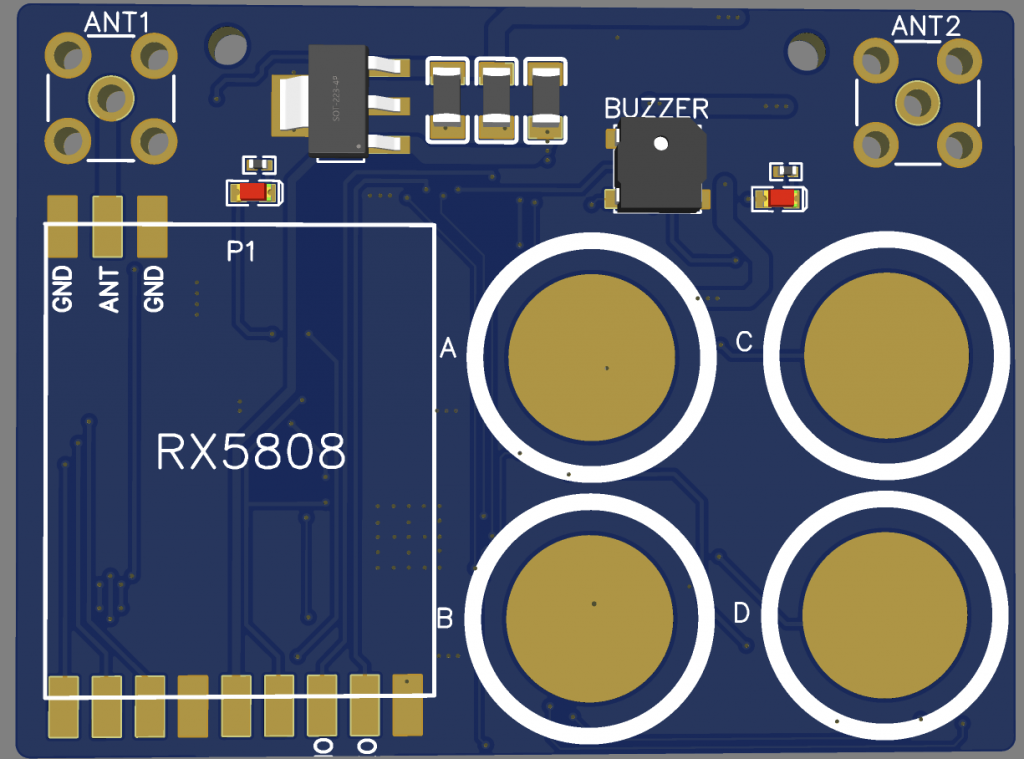
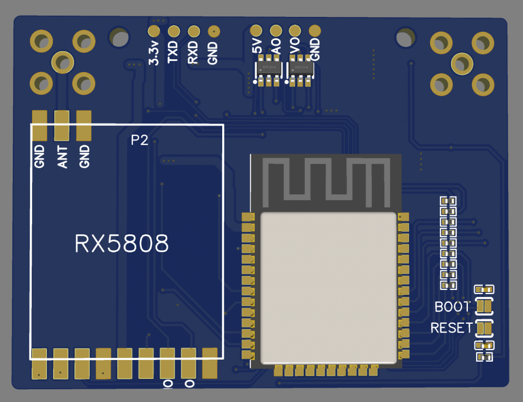
Recently flying my nano quad, felt a bit scary without a second receiver on the goggle. I had to keep moving my head to get the best reception for the video feed. Finally, I learned about the little display thing on every one’s FPV goggle is actually dual RX5808 receiver with some firmware that keep switching to the best video feed signal. My Eachine EV-100 having dual antenna but is not a very good in handling diversity. I found a few good opensource projects and saw their designs very good but I need audio output as well for the receiver so decided to make my own version. The board already sent for fabrication and now left the firmware to be developed and make it working. I had already tested the tv composite output is working and is very fun to built this diversity vtx receiver. Wish me luck!
The specifications: – Dual RX5808 Receiver – Video Out – Audio Out – 4 Touch Sensors – minimal components – single PCB with dual layers – 5V input – Using software SPI mode – Buzzer – 2 LED indicators – OSD in display – Web OTA
Had done all my testing and flying on this version. Found some bugs and fixed it. The problem was during 3.6v and above the output will be getting higher linearly. So I had added a diode with a 0.6v forward drop voltage. This enables it to have a stable output at 3.3v.
This board design is only meant for 1S. Meaning operating voltage is in between 2.0v ~ 4.2v. Higher than that you need to modify the buckbooster part into a 3.3v LDO as well as the 5v power line to a 5V LDO. I modified this from OMNIBUSF4PRO to my custom made version. I removed SDCard as the blackbox to save more space for the All-In-One board.
For the USB port, I am not supplying the 5V to the board. It needs to be power up from the 1S battery. I dont want it to overload my laptop 5V to it or maybe accidentally shorted the board cause the laptop 5V logic all burned off. That is why I designed it not to supply to the board but needs to power up with the battery or some power supply regulator to the board before the USB port is recognized by the laptop or PC.
For the ESC part, is designed to be running on 1S. The MOSFETS are running at 5A maximum at continuous and pulse drain at 12A. Due to the ESC I had flashed with BlueJay, it should be able to handle a bit more then 5A. The trigger level (Vgs) of the MOSFET is very low, there isn’t need any MOSFET drivers. The only thing, we need to invert the output from one of the line to drive the P-MOSFET. If intended to driver higher current, try to find another type of MOSFET and replace it. The ESC design also can be used those single MOSFET rather 2-in-1 MOSFET. It will be bigger but reliability wise should be better. When designing a higher voltage ESC, meaning more than 1S, you will need higher current rating of the MOSFET and may need to add a driver or custom transistor to drive the MOSFET. I will be working on higher “S” ESC in near future. These designs are came from tinyPEPPER – https://fishpepper.de/projects/tinypepper/ with some modifications done to the schematic where it enables it to run at a very low voltage to provides stable 3.3v to the EFM8BB21F16G and is sharing with the main board FC’s 3.3v powerline. This will save some costs of making this FC. One 3.3v buckbooster that powers up the FC, Gyro, Baro, VTX, Cam, ESC and etc. It will not draw more than 1A as I had tested so far. The VTX is powered up by another 5V buckbooster power line. So is totally not affecting each other.
For the FC firmware, I am using INAV 3.0.1. I am a INAV fans. For betaflight it will work too but need to changed to OMNIBUSF4 board for the firmware.
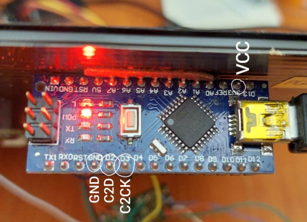
Initially, the ESC’s EFM8BB21F16G are blank. You need to flash in the firmware using C2CK and C2D pins before you can flash the ESC firmware over serial passthrough method. Once if flashed, all ESCs will be appeared in the INAV configurator. You even can use the BLHeli or BlueJay configurator to set your preferred settings. If you need to know how to flash in the ESC firmware, you can read from here -> https://www.bertfpv.com/how-to-flash-blheli_s-firmware-to-efm8bb21f16g/. You will be able to have a full control of your hardware and without fear of broken it again.
I will include the gerber file on the next version. For this version, I still need to fix the distance between the pads and the SMD components. It needs a very steady hand to solder the wires on it. So I am going to built version 2.0 very soon.
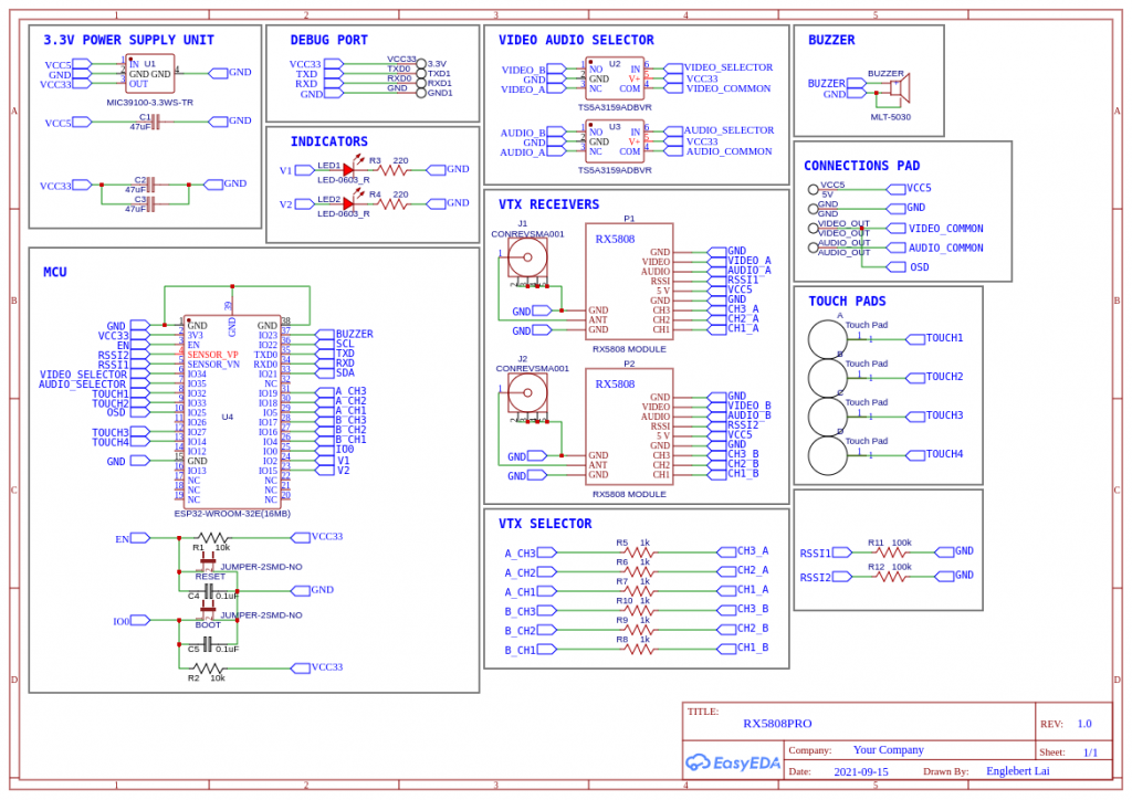
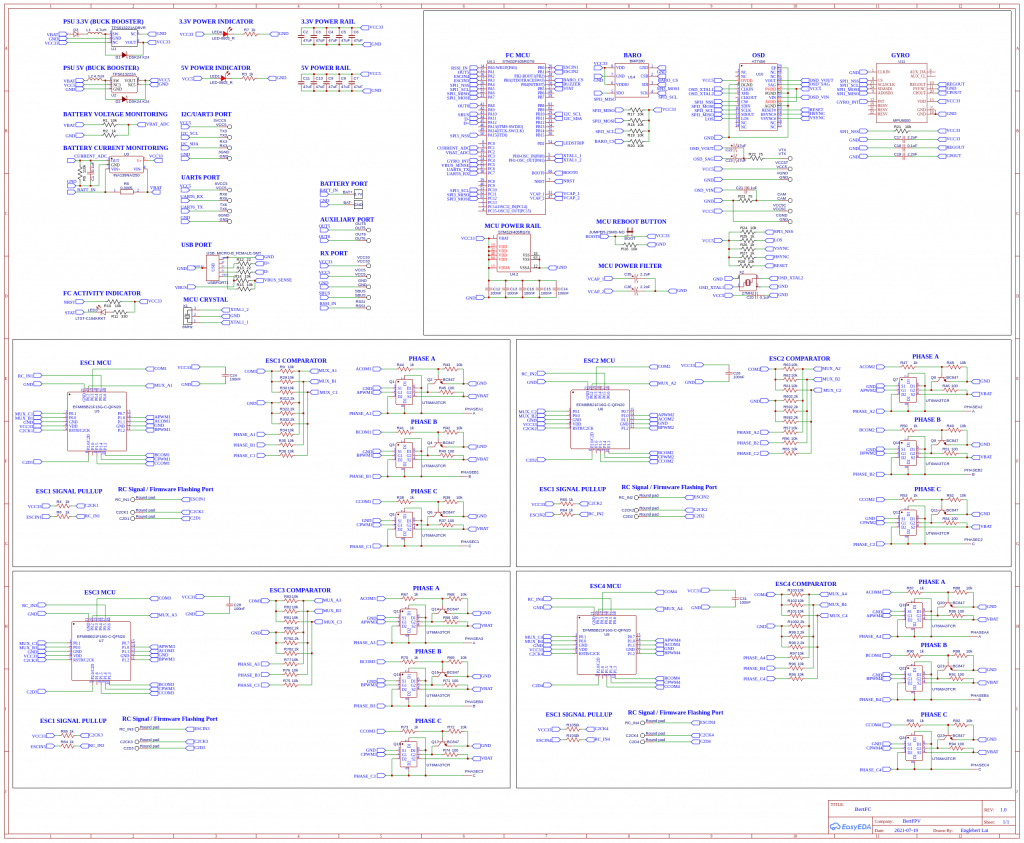
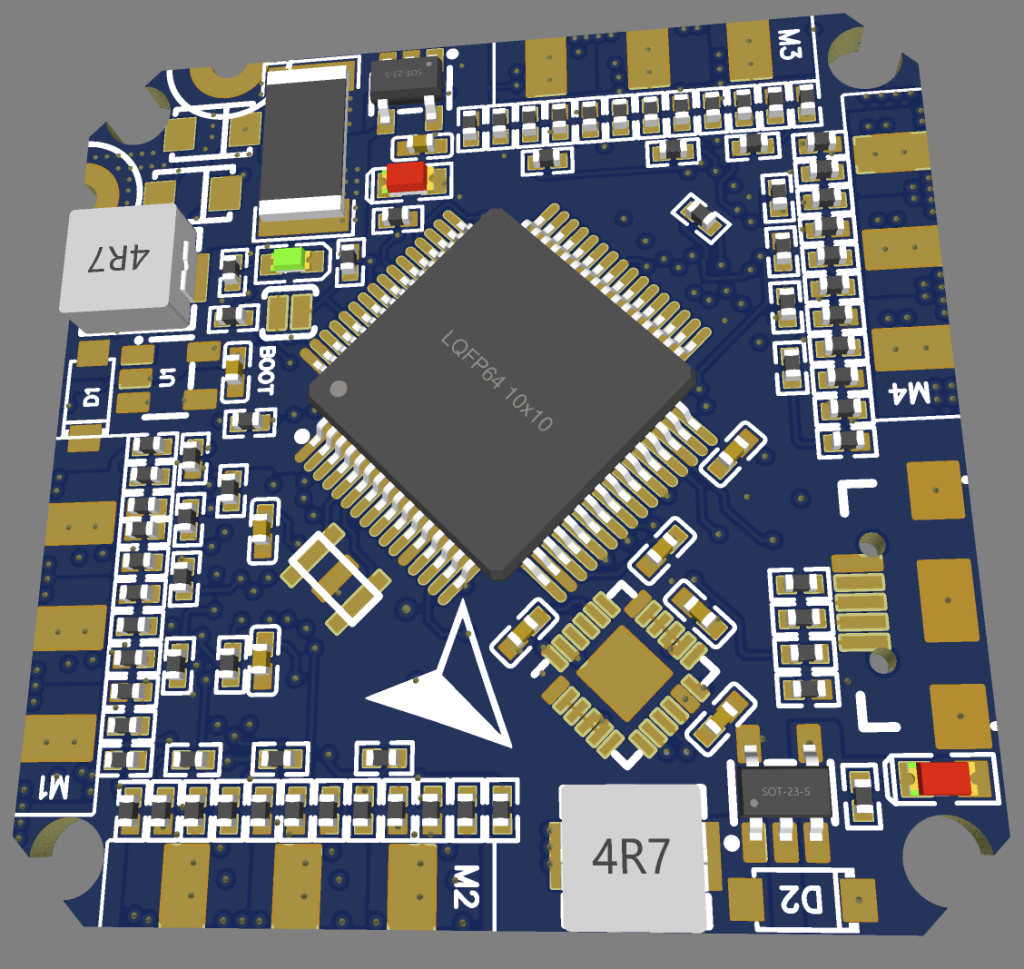
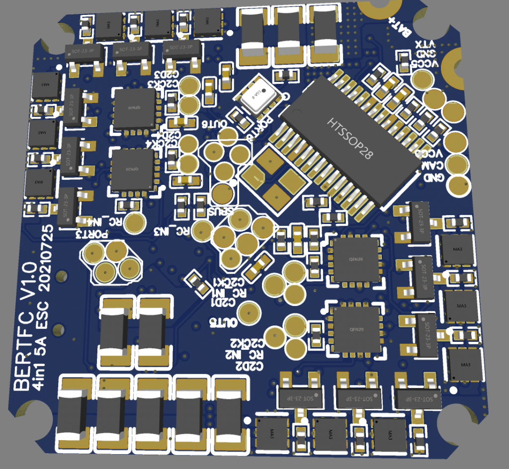
Below is the schematic diagram for this All-In-One flight controller I had built. I had included both PDF and PNG. Time to built it your own and fly it. Is a very great experience and understanding how the whole quad works. Stay tune.
Finally I am able to make it work on the ESC and flashed INAV into it. Testing out the functionality and the thrust power. The good news: IS WORKING! I am going to solder the rest of the components and make it fly…. Stay tune….
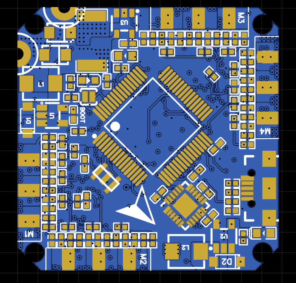
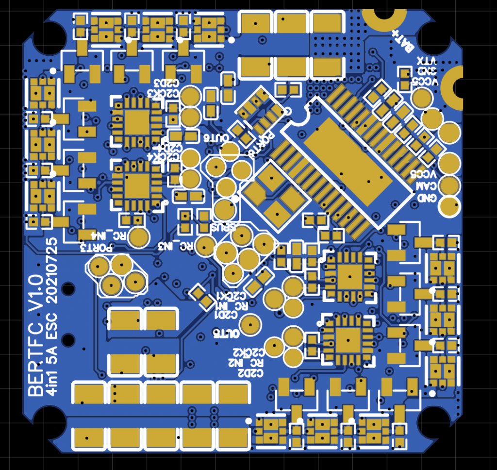
Finally have the full confidence that this version will be working well. As I am using the previous design as RnD and finalized the ESC is working and also corrected a few mistakes that I had done on the previous version. This coming version will be having: – 4-in-1 ESC with 5A on each channel (Good enough for a small 3-inch quads) – DSHOT600 is supported – BLHeli_S or BlueJay firmware are supported – STM32F405RTG6 as the heart of the Flight Controller – With a few serial ports for GPS – OnBoard OSD – SBUS protocol – Baro onboard – MPU6000 Gyro – Current Sensor – 3.3V buckbooster for all the ESCs, STM32 and etc – 5V buckbooster for VTX, Cam and GPS – Theoretically should be able to run from 2.0v ~ 4.2v. Yes, only 1S battery – 32.5 x 32.5mm
Why I build these? The reason building this is to understand how the whole quad system works. This let me dive deep into every aspect. I learned about ESC, ESC firmwares and also understanding how the ESC MOSFET works. The interesting part of this FC is low power. Normally FC using the cheaper version of the buck converter. I am trying to use a decent powerful buckbooster converter and hopefully this will let me to fly my quad for more than 20 minutes on single cell. All these ideas came from DaveC FPV which he had built a very nice Nano Long Range Quad running on 1S. This is the video -> https://www.youtube.com/watch?v=LDJBj7hRqW0. I would like to buy those FC but I just want to have something that I am able to build and opensource the schematic to everyone and build one for yourself. Once I am done, I will start to share out the schematic. Just need to make sure is working before sharing out.
Also, with this will let me keep on building more and more quads.
Below are the images of the board. Yeah, I just sent for fabrication and dont have the real thing yet. So stay tune, I will build and update again over here.
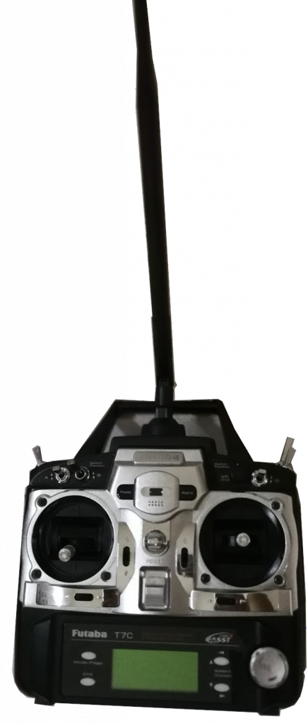
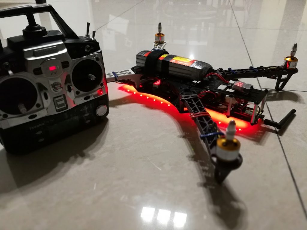
Since day one I am on this RC hobby, I never had any aftermarket Radio Controller Transmitter. I had bought a broken Futaba Radio Controller and stripped off all the components inside the case and just left only the toggle switches and the gimbals. I linked them to my arduino nano for the first version that I have. I was using a very long antenna to maximize the 2.4G range.
Version 1.0 – Running on Arduino, without removing the original display and with a long antenna.
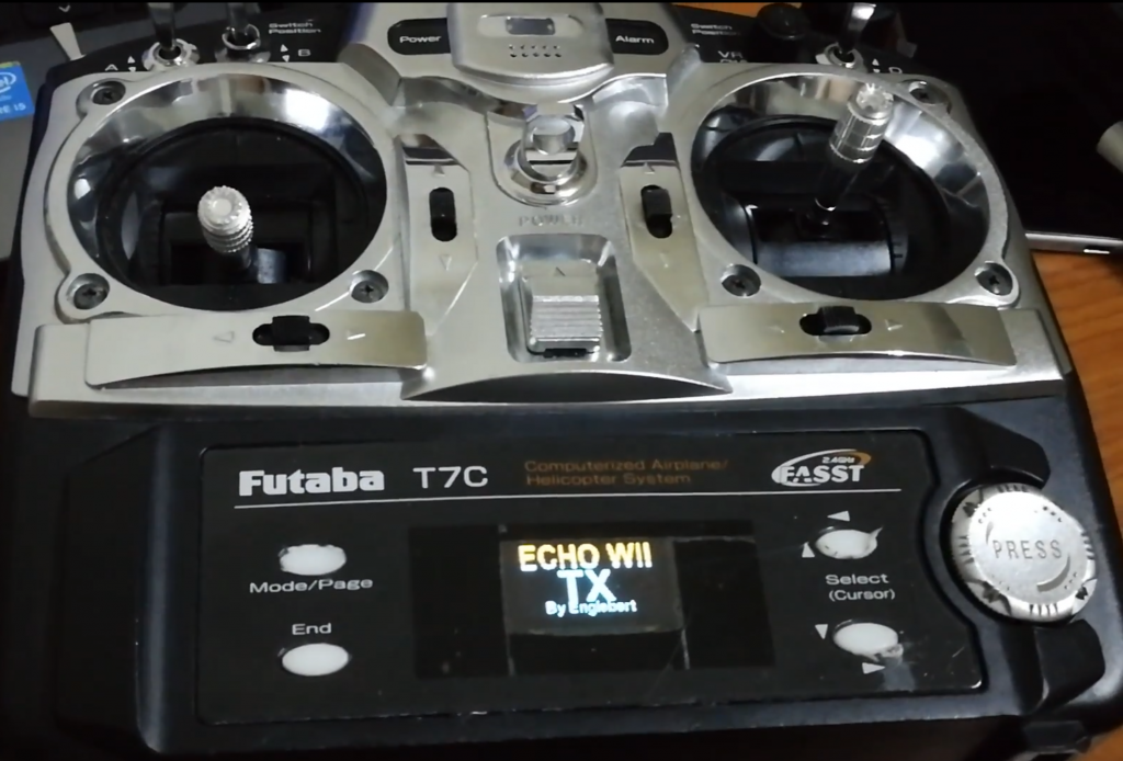
Later on, found that need a display to monitor the status and all the readings and decided to strip away the display and become a fully own custom version with display. Of course the case still a normal RC Transmitter case.
Version 1.1 – Upgraded with Buzzer and Display (OLED)
Had been using this a while and keep trying to learn flying at that time. Didn’t noticed about the precision I need that time. This Futaba gimbals are analog and the readings are about +-10% accuracy. Well, I was flying stable mode at that time and was enough for me.
This is the 1st quad I had build and flew with the barebone arduino with breadboard on it. Everything is hard wired. Wrongly match ESC with Motors. Kept burning ESC halfway in the middle of flying the quad until one day finally got it right. Big quads must use LOW KV, small quads must use HIGH KV. This will be another topic of it.
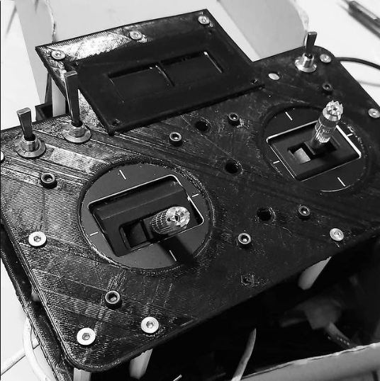
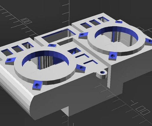
So once I am getting used to what I need, I had built a few racing quads with my own custom receiver and custom RC Transmitter. Until I had reached my limits and found out that actually I need something that are more precise in gimbal readings and faster processing microcontroller. I had upgrade from ATMEGA328 to STM32F1 chipset. But this also not for pretty long because I cant get what I need and the flexibility I wanted. Within the same year, I had upgrade to another version where the Radio Control Transmitter is totally 3D printed with FrSky M10 Gimbal Hall Effect sensor, ESP32, EByte E01-2G4M27D (Replica of nRF24L01) with 5km range and custom charging and 4 toggle switches. It was a development stage and the look of it like frankenstein because everything is opened.
The Frankenstein version.
It comes with dual OLED, for the fun of it and is running on ESP32 with BLE, WiFi and lots of computation power. I love this so much. The problem of this was a bit clunky and a bit opened. Very vulnerable from water that splashed in if is raining and so on. Well, I finally ditched off everything migrated to a better version and better designed of the Radio Controller Transmitter.
I designed this from scratch using OpenSCAD.
And the out come……
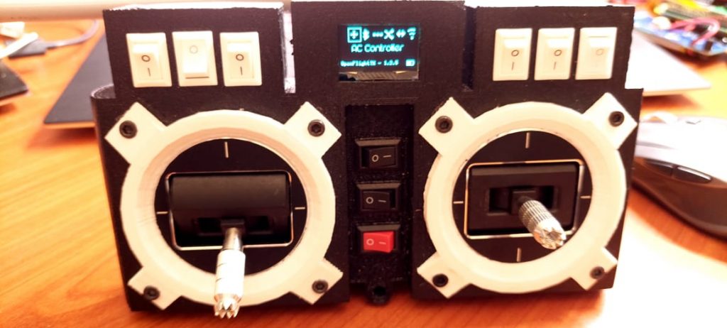
This is the latest version I have for now
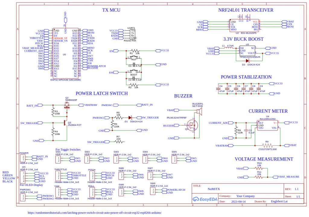
Yeah, A little bit difference but almost there. I used: – 9 Push switches 10x15mm – ESP32 16MB – 2 x FrSky M10 Gimbal Hall Effect Sensor – 1 x 0.96″ OLED – 30AWG silicon wires – 1 x 18650 Battery Holder – Custom design PCB and fabricated by JLCPCB – 1 x EByte E01-2G4M27D – Lots of SMD components (Look at the schematic)
I had perfected the menu display without using any buttons but using the gimbal to scroll through the items. Trying to save some I/O pins for the switches so I am having more channels to play with. I used to have a charger module built in with this but for this version I had removed it for the simplicity. Just charge the 18650 cell with a proper charger module and swap another piece if is low power.
WARNING: Still in progress of development. The current meter is not usable for this as the current draw was less than 1A. The designed was for quads that is draining > 1A. I will need to fix that and also the buzzer driver, I had put the MOSFET wrongly. I will need to change that in future. For now I had temporary disabled the buzzer. As well as the power latch section, I cant wait for the components arrival. I had altered to an ordinary power regulator module which stabilized the voltage from 4.2v -> 3.3v. The minimum operating voltage is about 3.5v as I had measured.
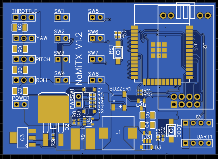
The PCB Layout
I will share the gerber later once I had perfected the issues.
Initial plan was thinking to have it run under 2.5v but the chip havent arrive until now. No worries, I am going to build some more with a better design soon.
Next topic will be the receiver and the details. I will write up and post it here as well as the code. The receiver is running on SBUS signal. Stay tune….
During the first time when I got my 1st ESC set up, I was stucked for a while and having a question in my head, ” How do I flash in the firmware?”. I am a pure Linux user. I don’t use Windows systems. Well, thanks to Google and I am able to find out a few ways. Somehow ended had to use the Windows Application and get the work done. In future, I will try to convert it to Linux when I have the time.
First get an Arduino Nano as the Interface module between BLHeliSuite and the Custom ESC. You will need to flash it with the provided HEX to the Arduino Nano.
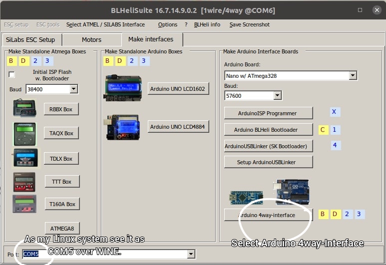
The above image indicates the PINS to be connected to the Custom ESC for the 1st initial firmware loading. Load up the BLHeliSuite and select the serial port that is connected to the machine also select the Arduino 4way-interface
Next load up the Choose firmware dialog box.
Select the 4wArduino_Nano__16_PD3PD2v20005.hex and click Open then flash the firmware into the Arduino Nano. This you will have the Arduino Nano to be the Interface medium between the BLHeliSuite and the Custom ESC.
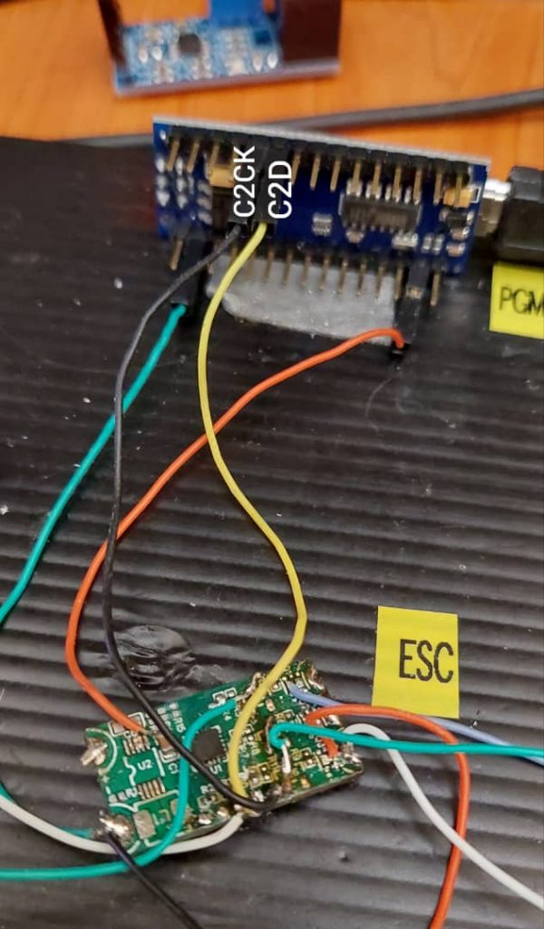
Below is the image on how to connect the wires to the custom ESC from the Arduino interface:
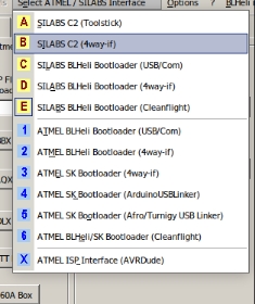
To load the initial firmware, you will need to pick the SILABS CS(4way-if) under the SELECT ATMEL/SILABS interface menu.
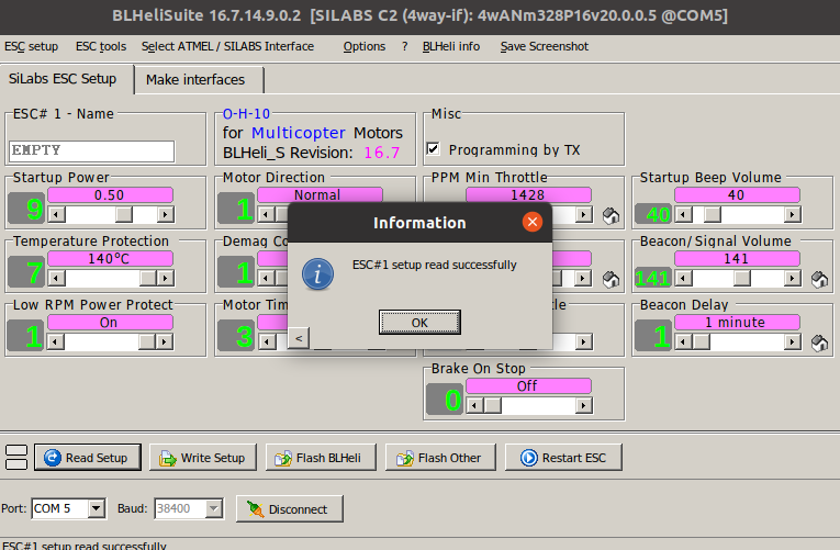
Select the right COM port and start to click on the CONNECT button and follow by the “Read Setup” button. If everything working, you will see something similar as below image.
From here, you can start to load up different firmware to experiment with the custom firmware to the custom ESC. Bear in mind, you may get smokes out of the MOSFETs. You will need to limit the current and voltage do to the settings and testings.
You can even swap the pins in the code and compile into HEX and upload to the ESC using this BLHELISuite. Of course, once this first initial version flashed in, you can start to use your FlightController to do a pass-thru for the firmware upgrades, settings and everything. I was testing on INAV 3.0 and it works great! Hope these will help some new comers whom wish to build and flash their own first firmware into a blank EFM8BB21F16G.
I had included the download link for users who interested to download and use it. For Linux users, can just use WINE to run it by typing “wine BLHeliSuite.exe” in the terminal to load the application up.
Stay tune for the next topic on how to compile and make the firmware.
Well, this site is to share all my RnD work to everyone who likes to build things from scratch. I am building drones since 6 years ago till now. At time my first drone was a big giant bird. I was using 500 X-Mode Alien Multicopter 500mm Quadcopter Frame. I picked that frame because the FC was just an Arduino running on MultiWii and some custom made receiver. Yeah, I am building everything my own even the receiver and transmitter. I developed the firmware for the receiver as well as the transmitter. Is using custom data packets using nRF24L01 modules. Now I am using EByte module which is identical to nRF24L01 and with more power you can go with. The fun thing of this hobby is letting you to build everything by yourself. Is a lengthy and long way to learn everything but is worth it. Trust me, is worth it. You will learn the electronics part, mechanical part and firmware developments. You can just buy DJI and fly but it will not last. You will get bored and forget about it. Building it your own will just let you keep this hobby non-stop on going to build more and more things on it. I will slowly share out all the things that I had built for this project from Custom Radio Controller, Receiver, FC and ESC. In order to learn more, you need to share more to others 😉
Finally came to an end where I need to redesign the schematic again for lesser components and trying to get power source from FC rather from itself. The whole idea is to cut costs and able to build it easily. Below is the diagram currently I am working on and going to test out the firmware on BLHELI_s with the version O_H_5 but with some minor modification on the code. I had accidentally swapped the pins at the MOSFETs side. Lets see how it goes once the board is back from JLCPCB.
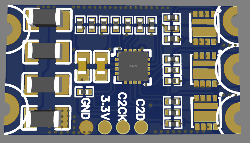
Below is the image of the ESC I had designed (Generated from EasyEDA):
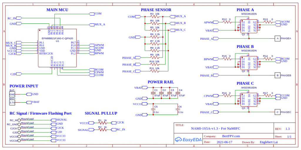
The Schematic:
As you can see, I am only using very little components here. Trying to make it as light as possible. Remember the power source for the ESC is from the FC. You need to build the FC with 3.3V and the raw power to drive the MOSFETs and motor.
The specification for this ESC design intended to run only on single cell and drain up to the lowest as possible. Below is the specifications of this design:
Operating from 0.8v ~ 4.2v (Theoretically from the buck-booster chip that I am using at FC). I would predicted as it will be flat at 2.5v as the minimum it can go.
Maximum rated 18A @ continuous and 45A @ pulsation mode.
Maximum support protocol upto DSHOT600.
Pass-Through mode supported through any FC. (Tested on INAV 3.0)
PCB designed only 2-Layers.
Only 1g for the weight of the ESC
Initial flash from C2CK and C2D pins for loading the firmware into the EFM8BB21F16G.
Now for the time being, I will just wait for the components arrival and start testing it and sharing the details again once I get the result.
Finally added a new repository server to my site. This will store all my source codes for the FPV related projects here. Freely shared to everyone to rebuild it. I will constantly update it. Stay tune.
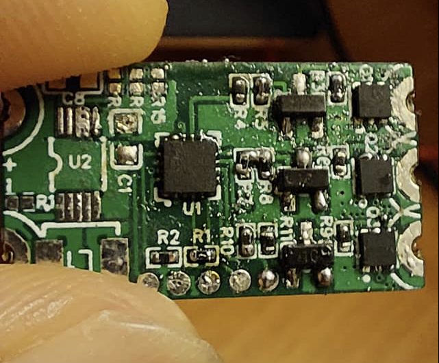
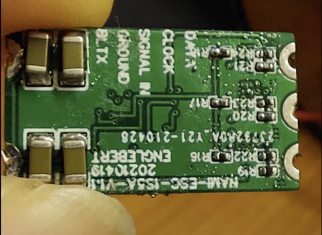
So far I had finished assembling the parts but still awaiting for some major parts arrival to confirm all the schematic are working before migrating to the All-In-One board. Front PCB: Back PCB: Is my first time working on 0402 size components. Still need to clean up those small dirty residuals from the paste. Also noticed that some of the parts still empty as I am still awaiting for the arrival of the components. That is the main buck-boost converter for this ESC project. As this ESC specification is as below: i. Operation Voltage: 2.5v ~ 4.2v ii. Operation Current: Maximum at 5A iii. BLHELI firmware compatible
Now still on development and going to test it for the functionality once done. Will keep you all posted.