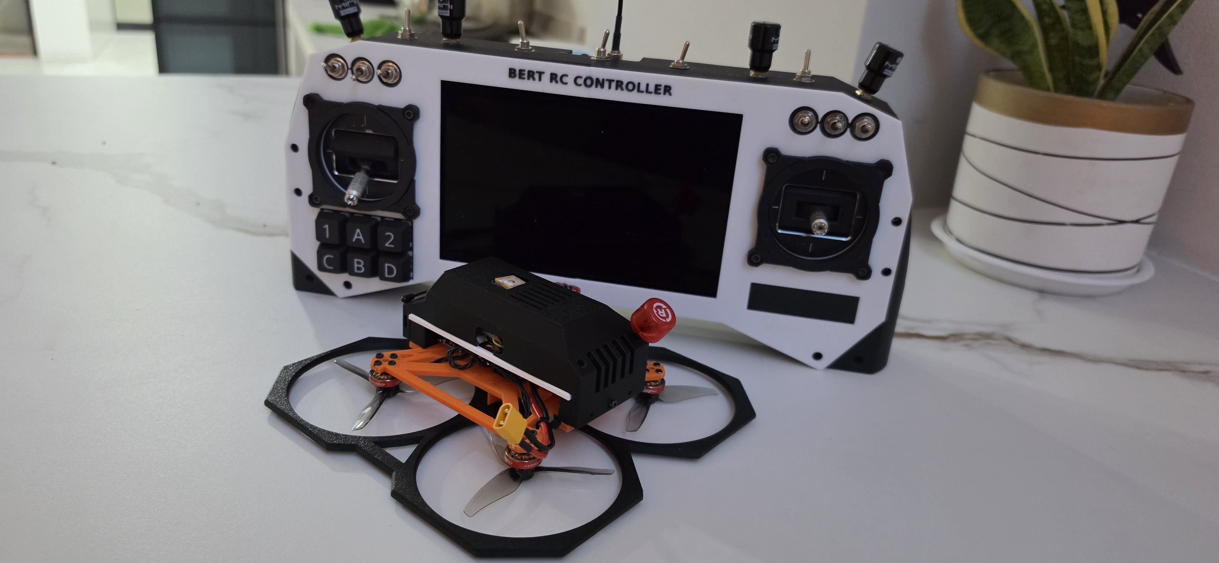
Everything is printed. Everything is wired. Everything is flashed.
After months of iterating on gimbal filtering, CRSF wiring, power rails and print revisions, both halves of this project are finally sitting on the table looking like actual products instead of a pile of loose boards and jumper wires. The transmitter shell is printed, the quad’s canopy is printed, even the prop guards are printed.
There’s still one thing left, and I’ll get to that at the end. But the build itself — done.

The air side: what’s inside the quad
The whole point of this airframe is that it isn’t running an analog VTX or a DJI-style closed system. It’s a Linux box that flies.
1. RubyFPV on a Raspberry Pi Zero 2W
This is the main objective of the entire build. The Pi Zero 2W sits inside the canopy running RubyFPV, handling the digital video link end to end. No proprietary bind, no locked-down goggles, no vendor deciding what my link is allowed to do. If I want to change the bitrate, the encoder settings, or the radio behaviour, I change it.
Going with the Zero 2W keeps the weight and power draw sane for a quad this size while still leaving enough CPU headroom for encoding.
2. JHEMCU GF30F722-ICM with custom Betaflight firmware
The flight controller is a JHEMCU GF30F722-ICM (F722, board target JHEF7DUAL) — but not running stock firmware.
I wanted proper current and voltage measurement from an INA226 instead of the board’s built-in ADC path, so I wrote the code into Betaflight to read the INA226 over I²C and feed those values into the battery and current sensor pipeline. That means the OSD, the telemetry going down the ELRS link, and the blackbox logs are all reading from a real high-side power monitor rather than an ADC divider and a shunt on the ESC board.
If you’ve ever chased a mAh-consumed figure that drifts 15% depending on how hard you’re flying, you’ll understand why I bothered.
3. GPS module
Standard but essential. With GPS on board the quad gets:
- Return to Home — the safety net that makes flying further out actually reasonable
- Altitude hold
- Position hold
For a build meant to go beyond line-of-sight on a digital link, this isn’t optional.
4. BetaFPV Nano ELRS receiver
2.4 GHz ExpressLRS for control. Fast, long range, and completely independent of the video link — which is exactly how I want it. Video and control failing together is not a failure mode I’m interested in.
5. MT3608 step-up: the trick that keeps the Pi alive
This is my favourite part of the whole power design, so bear with me.
The problem with running a Raspberry Pi in a quad is punch-outs. You slam the throttle, the pack sags hard, and your 5V rail dips just enough that the Pi resets — right when you’re moving fastest and least want to lose video.
So I don’t feed anything from the raw battery rail. Instead:
- Battery goes into an MT3608 2A DC-DC step-up, boosted to 9V.
- That stable 9V feeds the step-down converters.
- Those step down to a rock-solid 5V for the Pi.
- The flight controller is also fed the stable 9V from this module.
The result: even when the pack voltage collapses to 5V — well into “you are not flying anymore” territory — every piece of electronics on board is still running perfectly. The FC stays alive, the Pi stays alive, the video link stays alive. The quad stops flying long before the avionics stop working, which is exactly the order I want those two things to happen in.
This matters more than it sounds. It means a brownout-induced video cut and a failsafe are no longer the same event.
6. 3A 5V DC-DC module
Feeding the Pi and the BL-M8812EU2 WiFi adapter needs real current headroom, not a 1A module running at its limit. The 3A buck handles both without sagging.
The ground side: BERT RC Controller
The transmitter is the half that took the longest, because it’s not a modified radio — it’s a radio I built from the board level up.
1. RubyFPV on a Raspberry Pi 4B
The ground station runs RubyFPV on a Pi 4B. More CPU than the air side because it’s doing the decode, the OSD compositing, and the menu system.
2. Two × BL-M8812EU2 adapters
Dual RTL8812EU adapters for the video link. Two radios means diversity — better link margin and fewer dropouts when the quad’s orientation puts an antenna in a bad spot.
3. BetaFPV ELRS Nano 2.4 GHz TX module
The control link, wired as half-duplex single-wire CRSF into the ESP32’s UART2, running at 921600 baud. The module is powered from the 2S pack directly, not from 3.3V — that caught me out early on.
4. ESP32
The brain of the transmitter itself. It reads the gimbals, reads the switches, and builds the CRSF frames going to the ELRS module.
5. 2.25" ST7789 TFT (76×284)
A small SPI colour panel for radio status — battery, link, mode, channel state. It’s a bar-shaped panel, which suits a radio front panel far better than a square one.
6. Custom RC firmware
I wrote the transmitter firmware myself. It reads the Hall-effect gimbal signals through the ESP32’s internal ADC, runs them through a median-plus-EMA filter to kill the jitter, and packs them into CRSF frames for the ELRS module — with 10 channels of toggles mapped from the physical switches.
Writing your own transmitter firmware means every switch does exactly what you decided it should do, and nothing is buried three menus deep in someone else’s UI.
7. Six-key keypad for RubyFPV
The 1 A 2 / C B D keypad on the left is dedicated to driving the RubyFPV menu system. No fumbling for a separate keyboard at the field, no reaching around the back of the ground station. Menu navigation lives on the radio where it belongs.
8. Power: 4 × Molicel P30B in 2S2P
Four Molicel P30B 3000 mAh cells arranged 2S2P — 7.4V nominal, 8.4V charged, 6000 mAh. Plenty of runtime for a full session without babysitting the pack, and the P30B’s discharge capability means the Pi 4B and both WiFi adapters never see a sagging rail.
9. Seven-inch 1080p 120 Hz display
The screen is a 7-inch 1080p 120 Hz panel. The 120 Hz part is deliberate: a higher refresh rate means less time sitting in the display’s own buffer before a frame reaches my eyes. In theory that shaves latency off the end of the chain and helps reaction time.
Every millisecond in the glass-to-eye path is a millisecond you can’t get back anywhere else in the system, so it seemed worth spending on.
What’s left
One thing: the battery clamp.
The pack currently needs a proper printed clamp to hold it securely in the transmitter — right now it’s the last piece of the build that isn’t purpose-made. That’s the next design job, and then this project is genuinely finished.
Closing thoughts
What I like most about this build isn’t any single component — it’s that there’s no black box in it anywhere. The video link is open source. The flight controller firmware is a fork I compiled myself with sensor code I wrote. The transmitter firmware is mine. The shells, the canopy, the prop guards are all printed from my own designs.
When something misbehaves, there’s always a file I can open and a line I can change. That’s the whole reason to build instead of buy.
Files and firmware notes for this build are coming — if there’s a specific part you want documented in more depth (the INA226 Betaflight patch and the CRSF wiring are the two most likely candidates), let me know and I’ll write it up next.