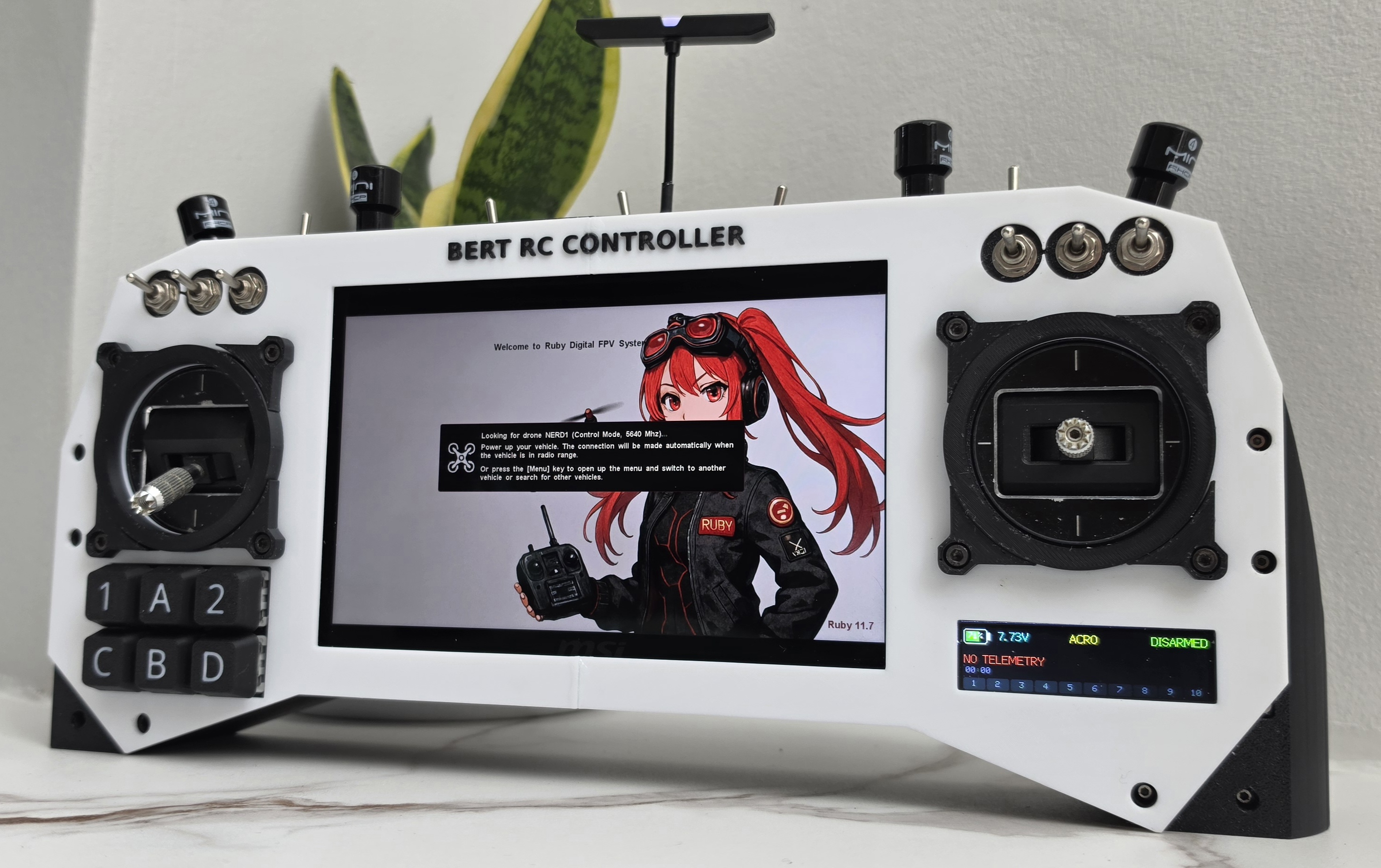
When I introduced the BERT RC Controller, I described it as two brains in one handheld — an ESP32-based radio transmitter fused with a RubyFPV HD video ground station. This post is the deep dive into the transmitter brain: every part, every wiring decision, the power architecture, and the firmware design that ties it all together.
If you’ve ever wondered what it actually takes to build your own ELRS handset from scratch, this is the whole picture.
System Overview
The transmitter side is built around a classic ESP32-WROOM-32 (dual-core LX6) running Arduino C++ on FreeRTOS, built with PlatformIO. It talks to a BetaFPV Nano TX V2 ExpressLRS 2.4 GHz module over CRSF, reads two Hall-effect gimbals through the ESP32’s internal ADC, scans ten toggle switches through an MCP23017 I/O expander, and drives a 2.25" ST7789 TFT for telemetry and radio status.
Alongside it lives the ground station: a Raspberry Pi 4B (2GB) running RubyFPV with dual BL-M8812EU2 Wi-Fi modules for long-range HD video, feeding a 7-inch 1080p 120Hz IPS touchscreen. This post focuses on the transmitter; the ground station gets its own write-up.
Parts & Modules
| Module | Role |
|---|---|
| ESP32-WROOM-32 dev board | Main MCU — RC firmware, UI, CRSF |
| BetaFPV Nano TX V2 (ELRS 2.4G) | RF link, JR-bay module |
| 2× Hall-effect gimbals | Throttle/yaw + pitch/roll |
| MCP23017 | I²C GPIO expander — all 10 toggle switches |
| ST7789 2.25" TFT (SPI, 76×284 bar panel) | Telemetry & status display |
| INA226 + 0.025 Ω shunt (2× 0.05 Ω parallel) | Pack voltage, current, and power monitoring |
| 5V 5A DC-DC buck module | Main power conversion |
| 2S2P Li-ion pack (Molicel P30B 18650) | Power source |
| 6× momentary buttons, 10× toggle switches | Controls (6 switches front, 4 top edge) |
Power Architecture
Power was one of the areas I spent the most time on, because a transmitter that browns out mid-flight is worse than useless.
The topology ended up clean: the 2S2P 18650 pack feeds a 5V 5A buck module, and the buck feeds the ESP32’s VIN. The dev board’s onboard regulator then produces the 3.3V rail for the MCP23017, both Hall gimbals, and the ST7789 — roughly 60–100 mA of peripheral load, well within the regulator’s comfort zone even with WiFi burst spikes on top.
Two important exceptions to the 3.3V rail:
The ELRS module does not run on 3.3V. The Nano TX V2 wants 7–13V on its VBAT pin, so it’s fed straight from the 2S pack through the JR-bay — with a 470 µF cap nearby to soak up TX power bursts. A 100 µF cap sits near the display for the same reason.
Battery monitoring originally used a resistor divider into GPIO36, but I dropped that entirely once the INA226 went in. It sits high-side on the main + rail, measuring across a shunt made of two 0.05 Ω 2512 resistors in parallel — 0.025 Ω, giving roughly 3.28 A full-scale. It reports voltage, current, and power over the same I²C bus as the MCP23017; one sensor replaced the divider and freed the GPIO for gimbal duty instead.
How long does it actually last? The pack holds 41.8 Wh on paper, and realistically you get 39–40 Wh back out on discharge. Divide that by the handset’s roughly 15 W draw and you land on about 2.7 hours — but that ignores the buck, which is only 85–90% efficient. Fold that in and the honest number is 2.3 to 2.6 hours, and even that assumes you’re willing to run the cells all the way down to 3.0 V each. Call it a comfortable flying day with the charger left at home.
One subtle gotcha: buck converter switching noise can leak into the Hall sensor ADC readings. Each wiper gets a 1 kΩ series resistor and 100 nF to ground as an RC low-pass, the pots are referenced to the clean 3.3V rail, and the filtering pipeline (below) cleans up the rest in software.
Wiring Reference
Here’s the whole thing on one sheet — power distribution and every peripheral connection, color-coded by net. Pin numbers are ESP32 GPIO:
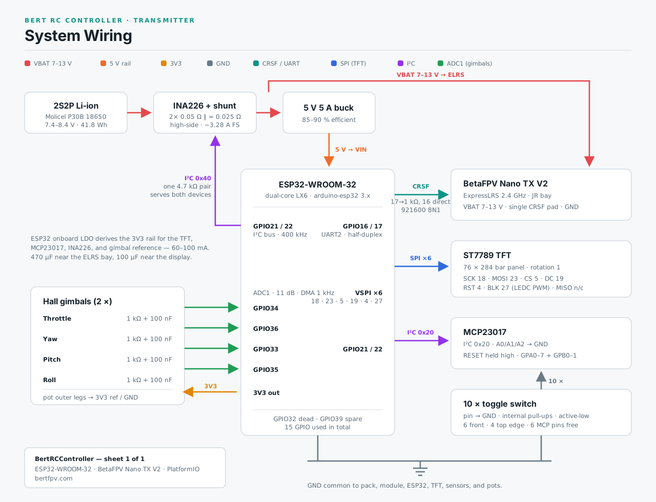
A few notes on how the pin map ended up this way, after ruling out every trap the ESP32 sets for you — ADC2 conflicts with WiFi, strapping pins 0/2/12/15, and UART0’s pins 1/3. All four gimbal channels live on ADC1 (GPIO34 throttle, GPIO36 yaw, GPIO33 pitch, GPIO35 roll — GPIO32 on my board turned out to be dead, so GPIO36 took its place once the battery divider was gone). None of the switches touch the ESP32 directly: all ten route to the MCP23017 at 0x20, and the INA226 shares the bus at 0x40 with a single 4.7 kΩ pull-up pair serving both.
The CRSF Link — Half-Duplex on One Wire
This was the most interesting engineering problem of the build. The Nano TX V2 exposes exactly one CRSF pin — a single bidirectional 3.3V UART line carrying RC channels out and telemetry back.
The wiring trick is passive half-duplex: GPIO17 (TX) through a 1 kΩ series resistor onto the CRSF pad, GPIO16 (RX) connected directly to the same pad. When the ESP32 transmits, the resistor lets the module win if it ever drives the line; when the module talks, the ESP32 hears it on RX.
Protocol details that matter:
- 921,600 baud, 8N1, non-inverted — no inverter or level shifter needed. CRSF’s baseline is 420 k, but the Nano TX V2 negotiates faster rates happily, and 921600 leaves far more slack in the 4 ms window for telemetry to come back between channel frames
- Frame format
[addr][len][type][payload...][crc8], CRC8 DVB-S2 (poly 0xD5) over type + payload - RC channels go out as type
0x16frames every 4 ms (250 Hz): 16 channels × 11 bits packed into 22 bytes, CRSF scale 172–1811 with center at 992 - Telemetry comes back on the same wire — link statistics (
0x14) with RSSI/LQ/SNR, and battery frames (0x08, big-endian)
The #1 failure mode of this whole arrangement: echo. Because TX and RX share one wire, every byte you send comes straight back at you. The CRSF driver has to discard exactly the number of bytes it just transmitted before parsing telemetry — if telemetry ever mysteriously dies, echo counter desync is the first suspect.
I map 14 of the 16 channels: four gimbal axes as AETR on channels 1–4, and the ten switches as AUX. Throttle failsafes to minimum (172) at boot — the module will happily forward whatever you pack, and a mid-stick throttle default on a bound quad is a surprise nobody wants.
Gimbal Reading — ADC Pipeline & Filtering
The gimbals originally had an ADS1115 external ADC pencilled in, but the ESP32’s internal ADC1 turned out to be entirely adequate once driven properly — so the ADS1115 got dropped, simplifying the BOM.
The firmware uses the analogContinuous() DMA driver (arduino-esp32 core 3.x — a hard requirement; PlatformIO’s stock platform historically shipped 2.x, which lacks it) sampling all four channels at an effective 1 kHz per channel with 11 dB attenuation for the full pot swing.
Raw ADC readings then run through a three-stage pipeline per channel:
- Oversample the DMA results
- Median-of-11 on a sliding ring buffer — sorting a copy each read, never the buffer itself, so time order is preserved. This kills spikes.
- Light EMA for final smoothing
Median first, EMA second — spike rejection before smoothing. The median stage introduces about 5 samples of group delay, which is why the sample loop stays at 1 kHz or above: total added latency stays bounded at a few milliseconds, imperceptible on the sticks.
FreeRTOS Task Design
The dual-core layout keeps the flight-critical path isolated:
- Gimbal task — pinned to core 1, highest priority. It blocks on a task notification; the ADC done-callback fires
vTaskNotifyGiveFromISR()and nothing else (no reads, no printf, nothing blocking in the ISR). On wake it drains the DMA buffer, demuxes by pin, runs the filter pipeline, and writes a shared 4×int16 struct guarded by a critical section so all four channels update atomically. - CRSF/ELRS task — core 0, reads the shared struct when packing frames, transmitting at 250 Hz.
- Display/UI task — core 0, lower priority, rendering telemetry from the CRSF task onto the ST7789 (backlight on its own LEDC PWM channel for dimming).
Since every analog channel lives on ADC1, WiFi doesn’t conflict with the sampling even if it’s ever enabled.
Where It Stands
Switch scanning through the MCP23017 with live status on the display is tested and working. The CRSF driver is talking to the Nano TX V2, with telemetry flowing back on the shared wire. The INA226 gives real pack numbers instead of a noisy divider estimate.
Still on the list: phase-locking transmit timing to the module’s 0x3A sync frames the way EdgeTX does, and implementing CRSF device/parameter frames — which would let me change packet rate and TX power from my own ST7789 UI, essentially reimplementing the ELRS Lua script natively. That’s a meaty follow-on project.
Next post: the RubyFPV ground station side — the Pi 4B, dual BL-M8812EU2 modules, power design, and getting a 7-inch 120Hz panel running in the field.
Follow the build on Instagram @englebert_fpv.